New
- Accuracy
- 0.015 mm
- Volumetric accuracy
- 0.015 mm + 0.035 mm/m
- Speed
- 6.3 M pts/s
Accuracy and volumetric error, the measuring instruments register, repeatability, markers and photogrammetry, resolution, speed and scan area: how to read the specifications of a handheld 3D scanner.
Quality control of manufactured products is one of the key factors in raising competitiveness, especially in mechanical engineering. For a long time, the most sought-after tool for measuring small and medium-sized parts, alongside hand tools, was the coordinate measuring machine (CMM). While hand tools offered quick geometry checks that depended on many factors, above all the operator's skill, the CMM, even at the cost of time, delivered the most complete and reliable information about the measured object.
New manufacturing technologies, advances in instrument making, growing demand for reverse engineering and increasing computing power have driven the spread of new measuring tools. They combine mobility, high speed, ease of use, completeness and accuracy of the acquired data, and versatility. All of these qualities are found in the subject of this article: metrology-grade handheld 3D scanners.
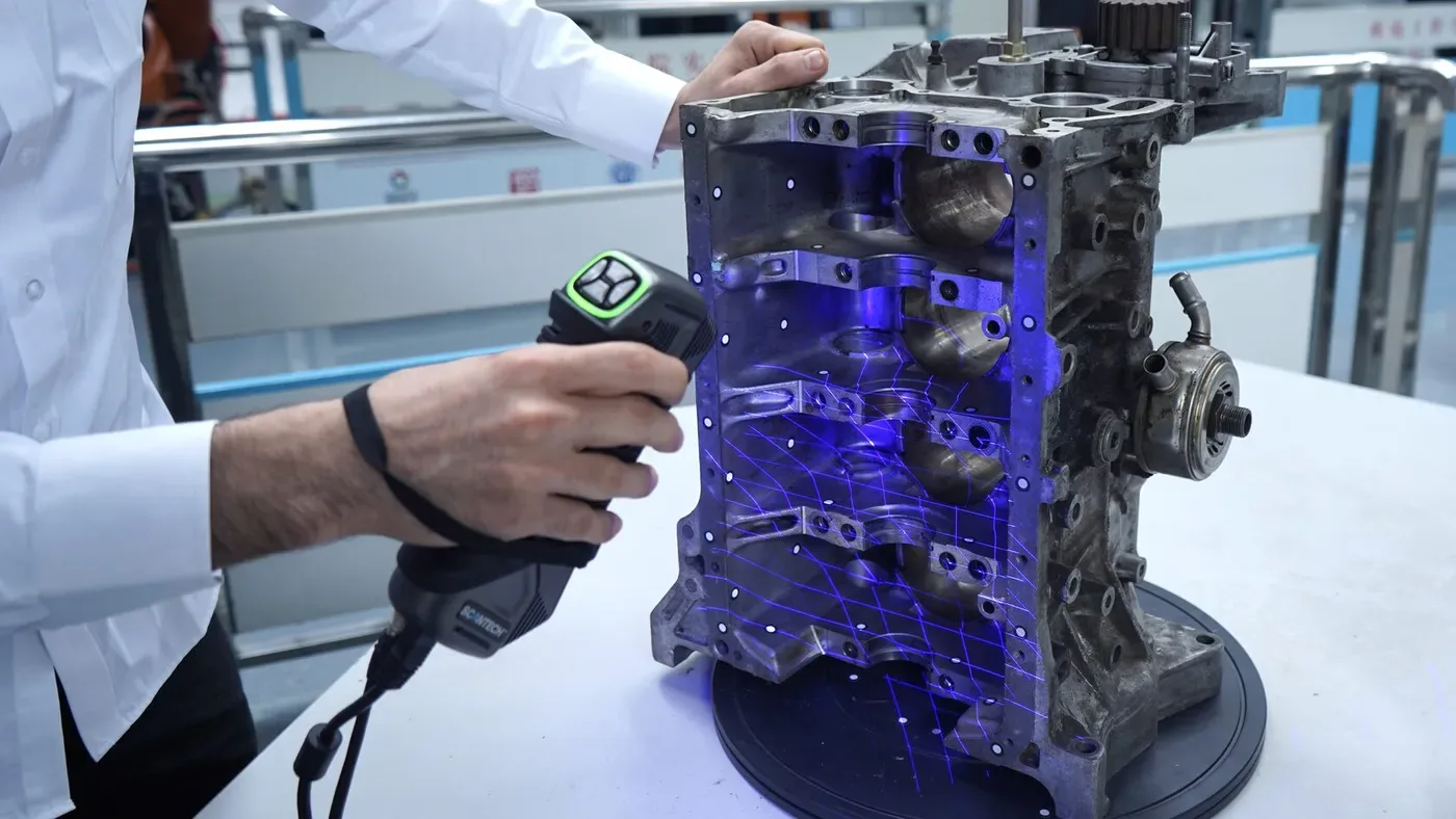
A handheld 3D scanner is a portable device designed to create a 1:1 digital copy of a real object with a small error.
It works by capturing, with industrial cameras, the projection of an image emitted by a light source onto the object, be it laser lines or structured light, and converting the captured data into a point cloud [Patent US10309770B2][Patent US8032327B2].
Measurements can be taken directly on site without fixed mounting. Handheld 3D scanners are easy to transport, need no tripods, and, compared with other high-precision measuring instruments, are more resistant to environmental factors, so they can be used outside the laboratory.
Latest-generation industrial cameras, blue laser lines, highly reflective markers and, in some models, processing units built into the device itself set metrology-grade equipment apart as a separate class of 3D scanners.
This is the key feature of 3D scanning that distinguishes it from all conventional measurement methods. In a short time it delivers not just a set of individual points or dry measurement figures, but a full digital copy of the object with all the geometric characteristics of the original.
All metrology 3D scanners work with reflective positioning markers (targets). Because the marker geometry is defined, the scanner can determine its position in space with high accuracy from the structure of the marker frame.
Most modern metrology 3D scanners can work together with photogrammetry systems. These systems, with a wide field of view and special scale bars, are used to capture the marker frame and reduce accumulated error, which improves the accuracy of the final data when scanning large objects. Some scanners also have built-in photogrammetry or video photogrammetry. More on this technology below.
When choosing a 3D scanner for inspection tasks, start from the characteristics of the object being measured: its size, tolerances and surface. Then select an instrument whose specifications provide the most suitable solution. In metrology, as one particular use of a 3D scanner, pay attention to accuracy (also known as the maximum measurement error), accumulated error, the light source, and whether the instrument is listed in the measuring instruments register.
The priority of individual scanner characteristics also varies by application area. In industrial design, for example, accuracy and versatility of the equipment come first, while ease of use is considered less important.
The key characteristic of any measuring equipment, showing the maximum error when measuring geometric quantities. It is important to read the specifications correctly and to distinguish the accuracy claimed by the manufacturer from the real measurement error of the instrument.
The former is usually written as "up to XX mm" and means that measurements may contain an error anywhere from zero up to the stated value, without guaranteeing that the error will not exceed it.
A more accurate picture of the instrument's capabilities is given by the maximum permissible error (MPE), also called volumetric accuracy, which consists of two numbers and is usually written as "XX mm + NN mm/m".
Here XX is the error of the handheld scanner without movement, and NN is the accumulated error, which grows as the scanner moves relative to the scanned object while capturing new markers.
It is common practice to count the first meter of movement regardless of the distance the instrument actually travelled. So if the scanner's certified volumetric accuracy is 0.040 mm + 0.060 mm/m, and while scanning, for example, an oversized object the scanner barely moved from its starting position, the data is considered to have been acquired with an error of up to 0.100 mm.
When we talk about a real maximum permissible error, we need a criterion for that reality. It is the accreditation of the measuring instrument in a metrology laboratory under internationally recognized standards, for example ISO 17025, VDI/VDE 2634 Part 3, ISO 10360 and ISO 10360-13. In the Russian Federation, for instance, there is an equivalent standard, GOST R ISO 10360-3—2017.
Recognition of a 3D scanner as a measuring instrument allows the manufacturer to state this in the specifications and allows the equipment to undergo verification, which is recorded in metrology reports as a certified measuring instrument. This gives the user confidence in the instrument and in the data it produces.
As a rule, the accuracy of a 3D scanner established by metrological testing for entry in the register is stated, according to the three-sigma rule, at a confidence interval of one, two or three sigma, i.e. 68.2%, 95.5% or 99.7% respectively.
The confidence interval thus serves as a marker of measurement repeatability. For example, if the instrument's maximum error confirmed by verification is 0.040 mm + 0.060 mm/m at two sigma, then during testing at least 95.5% of the measurements fell within the stated interval.
As mentioned above, the high accuracy of metrology 3D scanners is achieved in part through the use of reflective markers. As a rule, markers from different manufacturers do not differ in shape. Handheld scanners typically use 10/6 mm and 6/3 mm markers. The coating, however, and therefore the reflectivity of the markers, can differ. If reflectivity is insufficient, determining the marker position in space may degrade or become impossible, which either affects the accuracy of the data or makes the work difficult. We therefore recommend using markers from the same manufacturer as the scanner.
Photogrammetry, that is, capturing the marker frame with increased accuracy using a wide-angle camera, scale bars and, sometimes, special coded targets, is used for large objects (from 1.5 m) and can be implemented in 3D scanning in the following ways:
Standalone photogrammetry system
Supplied as a set consisting of a wide-angle camera, scale bars and special coded targets. The principle is to place the scale bars (at least two), stick coded targets among the standard markers, and then capture the marker frame by taking photographs. It should be noted that this process is rather labor-intensive, since a large number of shots from different angles and distances are required. The data is then transferred to the scanner software, after which scanning of the object can begin.
Built-in photogrammetry
The only difference from the standalone system is that the wide-angle camera is already built into the device, so the scanner itself passes marker frame data directly to the software. Like the first option, built-in photogrammetry slows down the work but improves the accuracy of the data.
Video photogrammetry (VPG)
The most convenient implementation of the technology. Like built-in photogrammetry, it uses the 3D scanner's wide-angle camera and scale bars and passes data directly to the software, but the important difference is that it works with standard markers. This difference is what sets the technology apart, as it gives a significant gain in both the accuracy and the speed of marker frame capture.
3D scanners with built-in photogrammetry or video photogrammetry can serve as a standalone marker-capture system for use with scanners from the same manufacturer that do not support these technologies.
An adjustable parameter that affects the level of detail of the resulting model. During scanning, the operator sets the distance between the captured points, from which a polygon mesh is later built, with an average triangle (polygon) edge length close to the set resolution.
High-resolution scanning is therefore required for oversized parts and for objects with small details.
Note that resolution does not directly affect the accuracy of the data, but a low value can distort the geometry, especially at corners, which indirectly degrades accuracy.
Some 3D scanners with limited camera resolution use special mathematical interpolation algorithms to compensate for insufficient detail in the source data by adding one or more calculated points between two actually scanned points.
The more detail is required, the more data has to be captured during scanning, which affects the speed of the process. Highly detailed models also take up a lot of disk space, and working with them in various software, both for inspection and for reverse engineering, requires a high-performance workstation.
The current system requirements for a workstation to work with modern metrology 3D scanners, at the time of writing, are listed below. Keep in mind that technology does not stand still, and it is better to consider configurations with spare performance for the future:
To simplify and speed up work with scan data, we recommend mesh optimization. This can be done in the scanner software and is used to reduce model size by enlarging polygons on flat areas.
Directly affects scanner performance, that is, the time needed to scan a part. It is usually expressed in points per second and depends on the light source and cameras used in the instrument.
In laser scanning, what matters is the number of laser lines, which determines how many points are "illuminated" in a single frame, and the camera frame rate, which determines how often those points are captured.
In structured light scanning, whether infrared VCSEL or white light, the point field is much larger, which lets these instruments scan faster and work without markers. However, this technology is of limited use in metrology tasks because of the lower accuracy of such instruments.
The area covered by the cameras at the focal distance from the object. It is usually written as NN x NN mm. It mainly affects how densely markers must be placed. For most metrology handheld 3D scanners it is roughly the same and equal to the size of an A3 sheet. The exceptions are:
Outside the cases described above, this characteristic affects neither scanning accuracy nor speed.
This article covers "classic" handheld 3D scanners. Given the volume of material and the nuances of the equipment, systems consisting of a handheld 3D scanner, an optical tracker and, sometimes, a probe will be covered in future articles. Stay tuned!
When analyzing the specifications of 3D scanners presented on manufacturers' official websites and in the accompanying documentation, we recommend paying particular attention to the parameters described in this article.
However, when choosing a professional metrology solution, we also recommend considering the following:
Our specialists will help you understand the specifications and choose a solution that fully meets your requirements in terms of both functionality and cost-effectiveness.
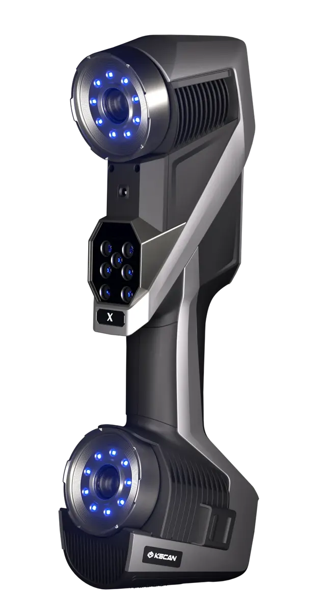
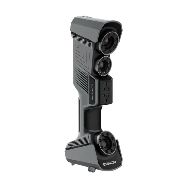
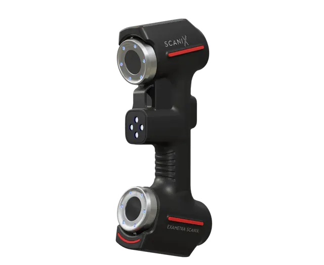
An EXAMETRA engineer will pick a solution and run a demonstration.
Full catalog